

A class diagram is a visual way of depicting the data to be held within a system, the way the various classes of data are connected and their relationship to each other. It is drawn using a standard notation; Unified Modelling Language (UML). Class diagrams can be useful to determine the data requirements of the new/current business system.
What is a class diagram?
A class diagram is a visual way of depicting the data to be held within a system, the way the various classes of data are connected and their relationship to each other. It is drawn using a standard notation; Unified Modelling Language (UML).
Why use a class diagram?
A comprehensive data model like the class diagram is useful for the following reasons:
- To determine the data requirements of the new/current business system. What particular data does the system need to store?
- To ensure a common understanding of all the data. This is crucial if different systems/components are to be sharing data between one and other.
- It can form the basis of the technical implementation; the class diagram being the initial blueprint.
It defines integrity rules about the data, with a structure of that reflects rules in the business.
How do you depict a class diagram?
Using UML, a class looks like the following:
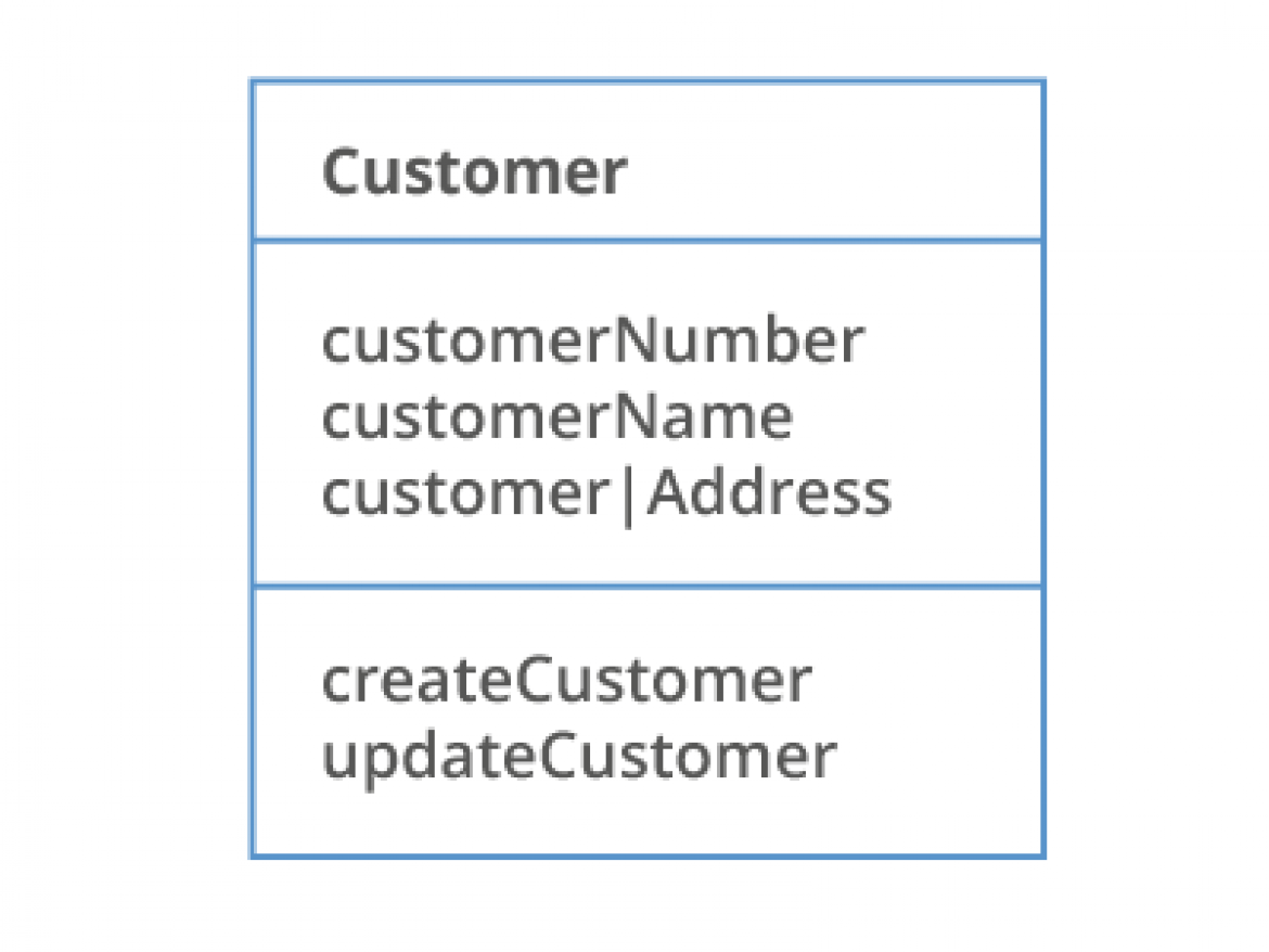
- This is a table with one column.
- Top cell has ‘customer’.
- Middle cell has ‘customerNumber’ the next line has ‘customerName’ and third line ‘customerIAddress’
- The bottom cell has ‘createCustomer’ and the next line has ‘updateCustomer’
Classes are groups of objects within a system that share common sets of features; attributes and operations. Attributes are individual pieces of data contained within that class and operations are messages sent to that class by other classes.
A class could be anything about which information is to be stored. In local councils, this could be customers, leisure events, council buildings etc.
To draw a diagram, a class is represented by a rectangular container, which contains the name of the class in the top compartment. The attributes are listed below the class, with the operations listed at the bottom. Classes are linked together by associations, which will be in the form of a meaningful business phrase linking two classes, for example:
Customer MAKES booking
Customer SUBMITS booking
To ensure effective communication of the class diagram between business and IT, it is critical that the associations are named clearly to reflect the business rules they support.
Numbers at each end of the class association indicate the range of numbers of instances of classes allowed in the relationship.
- This picture has two columns, one to the left and then one to the right with an arrow between the two saying ‘submits’.
- There is correlation between the two columns for example the first cell in one column says ‘planningApplication’ and in the other column it states ‘Customer’.
- The following cells follow the same pattern in terms of application number and then into createApplication.
Possible number ranges could be:
0.. 1 (Zero to 1)
0.. 10 (Zero to 10)
0.. * (Zero to many/unspecified)
1.. * (One to many/unspecified) etc.
So here with this example of a class association we see that the Customer (class) Submits (relationship) zero or one (multiplicity) Planning Applications (class).
- This picture has two columns, one to the left and then one to the right with an arrow between the two saying ‘submits’. It also includes numbers 0…1 to demonstrate the range of numbers of instances of classes allowed in the relationship.
- There is correlation between the two columns for example the first cell in one column says ‘planningApplication’ and in the other column it states ‘Customer’.
- The following cells follow the same pattern in terms of application number and then into createApplication.
Things to consider
Class models are used at the requirements definition stage. After completion, with a supporting requirements catalogue, these should be passed to IT to implement the required changes. Other system models such as use cases may also be required.